While I had done a few CNC projects using flat end mills, I had not learned the fun of v-carving. This is a method of using a v-shaped bit to make lines of varying widths by cutting deeper or shallower into the material. Typically it is used for lettering and graphics in signs.
Recently, someone contacted me and asked if I could show her how to use her CNC machine that she bought last year to make v-carved signs. I did as much study as I could through YouTube to learn about the software that came with her machine. During my time with her, I got a chance to enjoy the $700 software package that is VCarve Pro. It was fairly easy to understand and use. However, the price tag is much more than I wanted to spend for software that I might use a few times a year.
There are a few other programs that do similar things, but the one I have experience with is Easel Pro (which is the software of choice for my CNC). But at $25 a month for a feature that I might or might not use during the month, I was still left searching for something more reasonable (even if it wasn’t as easy to use).
I’m not against paying for software; especially software that could potentially help me earn money in return. It can be an investment. But, I’m not primarily looking to make money with my CNC projects. I do the projects I do mostly out of personal enjoyment.
Enter F-Engrave
I have seen F-Engrave come up as an open source option for a couple of years. But, it has also been terribly confusing for me to wrap my head around. Having enjoyed the ease of VCarve and the cool effect that v-carving can give, I had to take the time to figure this out.
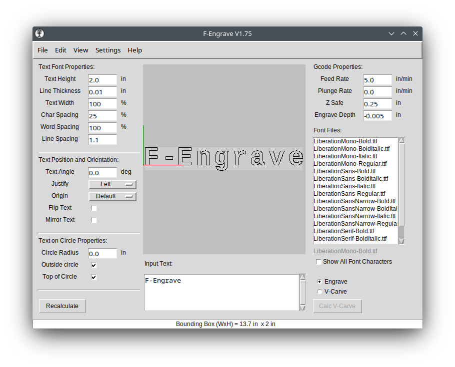
As is typical with open source software (I am a big fanboy), there is amazing power wrapped up in a less than stellar user interface. Front and center in F-Engrave is the ability to input text and carve it out all in one screen. However, this hides the fact that this is a powerful tool for creating intricate inlays and v-carving any design you can create in a design tool like Inkscape, CorelDraw or Adobe Illustrator.
I made a video on how to use the software, but also have written more detailed instructions here.
Importing Artwork
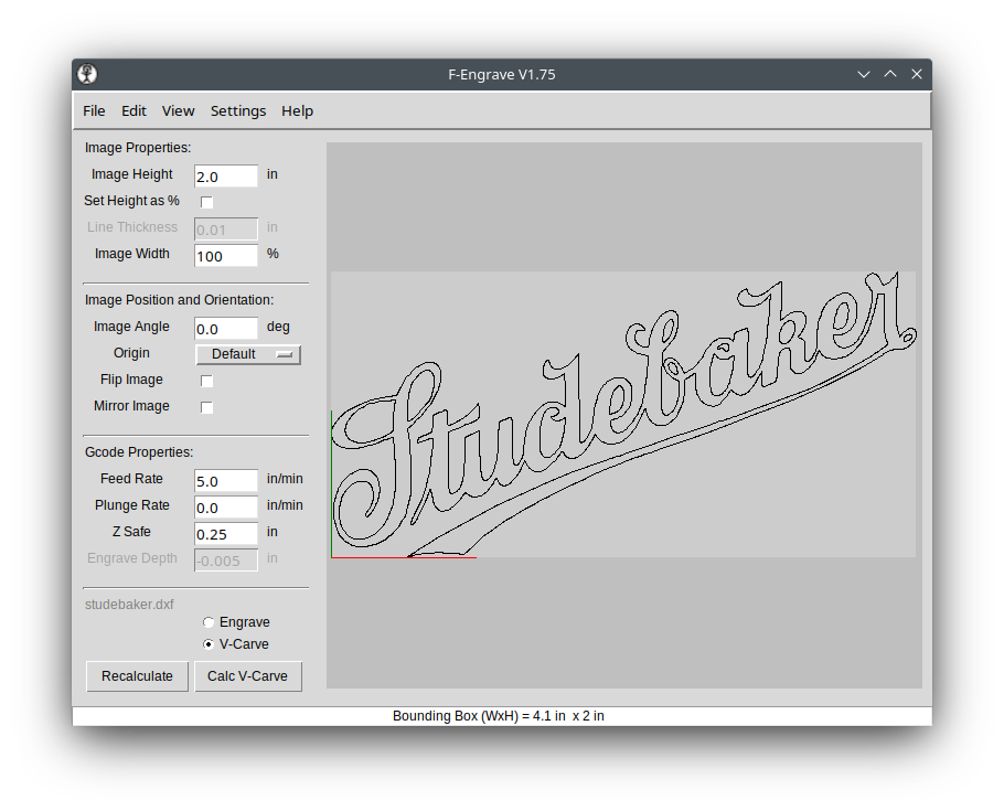
To import your artwork, you need to have saved it in DXF format from your design software. This can be text or actual art.
You can see I imported the Studebaker logo that I created in Inkscape by clicking File | Open DXF and navigating to my art to open it.
Settings Explained
Following are the settings that are needed to do a v-carve. However, I don’t completely understand every option the software has to offer. For example, everything we are doing here to create a positive v-carve can be inverted to make a perfectly fitting inlay. But I’m still trying to figure some of that out.
V-Carve Radio Box
At the bottom of the left-hand column, there is the V-Carve radio box. Select that. Even though it is the bottom of the column, it is important to choose that so that we have the correct options presented to us in the next steps.
Image Properties
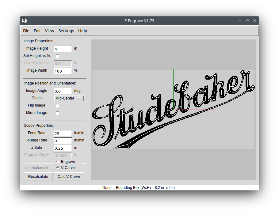
Image Height is the final height of your art on the work piece. This defaults to 2 inches and is probably something that you will need to change unless you actually want your final art to be 2” tall.
Set Height as %. I am not sure why you would use this. A percentage of what?
Image Width is in percentage, but that is in relation to the height. 100% means that it will be normally proportional to the image height. Less than 100 and the image will be scrunched left to right. More than 100 and it will be stretched.
Image Position and Orientation
Image Angle is used to turn the image from horizontal to vertical or any position in between. You can play with the number and see what that does. Typically, this will be left at 0.0.
Origin is where you want to set the X0,Y0 (work home position) on your CNC machine. Typically this will be the bottom left or center of your artwork. To start your origin in the bottom left corner choose Default or Bot-Left (the same thing when using art) in the drop down menu. For a center origin choose Mid-Center.
Flip Image and Mirror Image are used for inlays. You will probably not use these for normal v-carving. You can click the check boxes to see what they do.
Gcode Properties
This is where you set the speed and plunge rate of your travel moves.
For wood, I have been doing 25 in/min using an X Carve machine. If your CNC is a smaller desktop version you may want to go much slower than that.
Plunge Rate should be something in the 5-10 in/min range unless you know your machine can handle something faster. The default of 0 copies whatever the feed rate is that you set in the box above.
Z Safe is how high above the work piece the machine will move before a travel move.
Calc V-Carve
At this point you can hit the Calc V-Carve button and see the results of your settings. But there is another screen we must look at before you can save your project and cut your sign.
Settings | V-Carve Settings
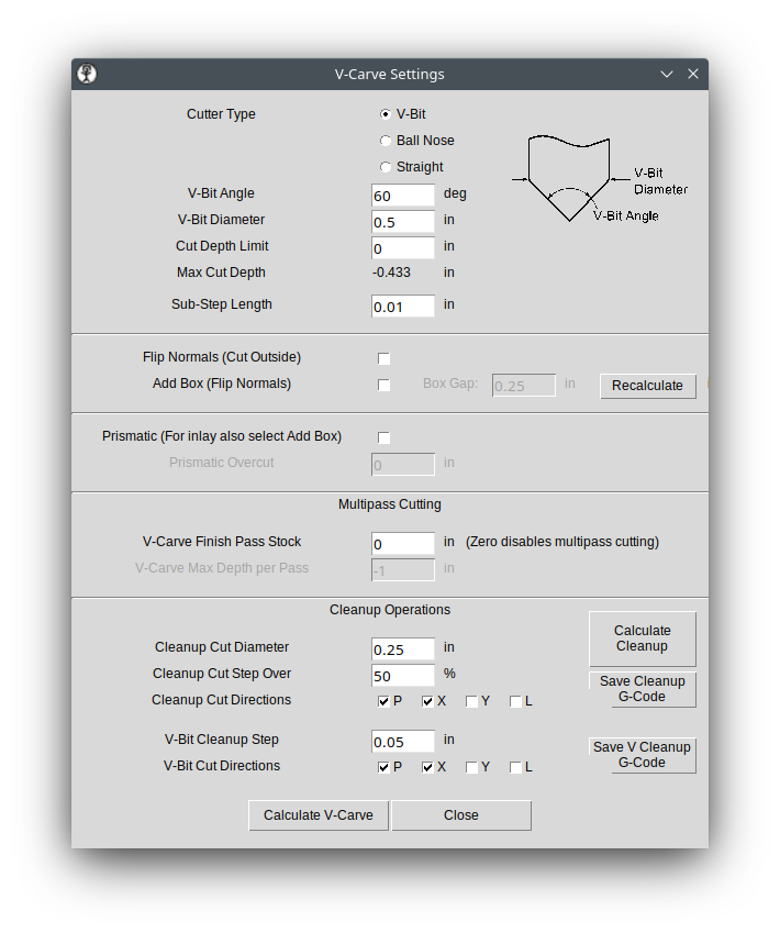
For our purposes, here are the things you need to choose and modify from the Settings screen.
Cutter Type will be a V-Bit. However, you can get similar but different results from the Ball Nose option.
V-Bit Angle is usually 90, 60, 45 or 30 degrees. Type in the angle of your bit.
V-Bit Diameter is the largest width of your bit. I usually use a ¼” router bit, meaning a ¼” shaft. But, that is not the number this option is looking for. This needs to be the size of the cutting area of the bit which will usually be larger than your bit’s shaft.
Cut Depth Limit is set to 0 by default. That means that the next line down is how deep the final cut will be. In my example it will be -0.433 inches. There is nothing you need to put in the Cut Depth Limit box unless the depth shown in the Max Cut Depth line is too deep for your material or deeper than you would like it to be.
If you need to adjust the Cut Depth Limit, then you need to type a negative number in the box.
At this point you could click the Calculate V-Carve button and be ready to save your gcode.
If Done, Save Gcode
On the main screen of F-Engrave you can click File | Save G-Code to save your code. The default file format is .ngc. That may or may not be readable by your CNC control software. If it is, then you can save the file in that format and then send it to your CNC.
In my case, my control software of choice (right now it is OpenBuildsCONTROL) does not recognize the .ngc format. But, you can also manually change the file extension to .gcode if needed. Either way, it is a simple text file that is being created.
Optional Steps
Cleanup
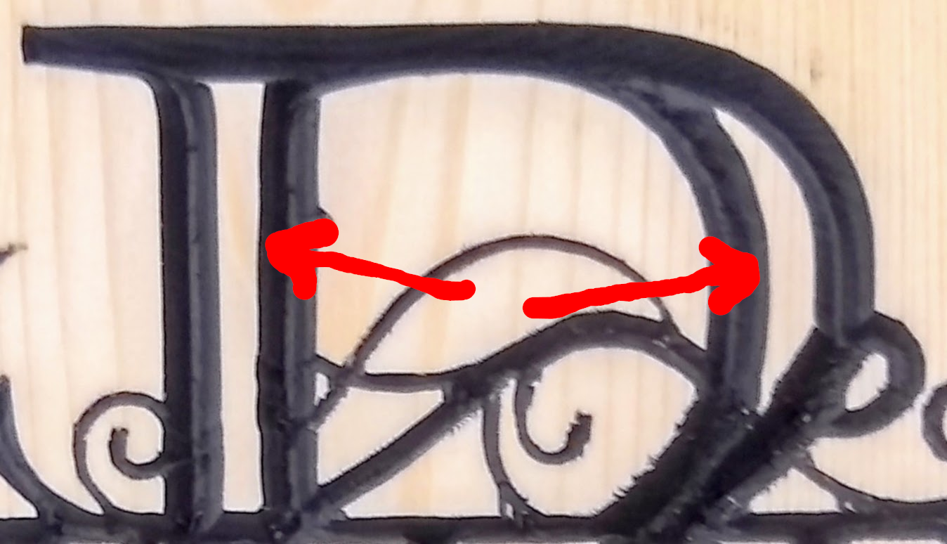
If, after calculating the v-carve you find that there are sections in your carve that have two white lines in a single section of the letter (like in the image below), then you will want to calculate a cleanup path.

Go back to the Settings | V-Carve Settings screen. At the bottom right you will see a Calculate Cleanup button. Leaving the settings at their default values, you can create a cleanup path that will use a ¼” end mill to flatten out the bottom of the carving. Why one would need to do this only became obvious to me once I did a cut that needed it.
In the following image the red arrows are pointing to areas within the letter that should have been carved out during the v-carving process. However, since the letter was so wide, the bit was not able to carve out the area needed without going too deeply into the wood. This is where a cleanup toolpath will flatten out that space inside the letter.
After clicking the Calculate Cleanup button, click Save Cleanup G-Code and save the cleanup toolpath. Again save it as an .ngc file or .gcode file as needed.
Run the main gcode file first on your machine, then the cleanup gcode after changing to a ¼” bit (or whatever size you specified in the Cleanup Cut Diameter box).
Settings | General Settings
In the General Settings dialog box you can choose whether your units are inches or millimeters. All the other settings are probably important for something, but I have yet to figure them out. You may need to adjust the G Code Header and G Code Postscript for your machine. I was fairly successful in finding what those fields do by searching on Google.
Final Steps
Take the gcode file that was created and run it on your machine by using the CNC control software for your machine. This may be Easel, Universal Gcode Sender, Mach 3|4, OpenBuildsCONTROL, Ready2Control, LinuxCNC or many other control software options.
Actually controlling and sending the code to your machine is beyond what I can do here and keep this general enough for all machines.
Other Features
The other great thing that F-Engrave can do, that I do not yet understand, is inlays. You are able to cut the inverse of the v-carve that we just did in another piece of wood and glue them together for a perfect match. Explaining that will have to wait until I get tired of this process and am ready to spend the time to learn the workflow. There are videos on this process, I just haven’t been able to wrap my head around the steps.
As mentioned at the beginning, I have done a video on the v-carving process that may be a bit easier for you to follow.